
YH2222A module
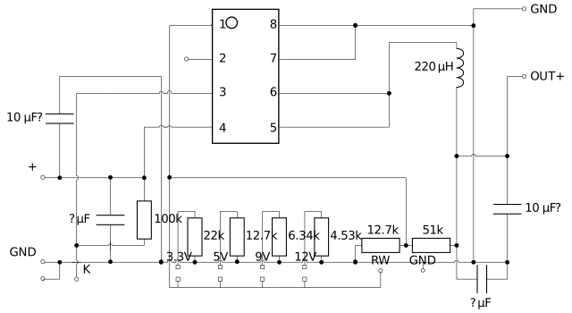 What the circuit looks like. Mistakes are possible.
This is a module that reduces DC voltage. For example, 12V to 5V.
It's an alternative to, for example, the "LM2596 module". Though note that that "LM2596" does not refer to TI's LM2596. Its operating frequency is different, etc.
It might have a flaw. The enable pin is connected to VIN through a 100k series resistor, and it is not connected to GND in any way externally. This means the enable pin might exceed the absolute maximum rating. However, a zener diode could be connected from GND to the enable pin, with "K", which is conveniently near the input ground.

It fits on a breadboard but it's not perfectly aligned.
If the input holes are 0 holes away, then the output holes are about 8 holes away across the length and about 2 holes across the width.
Its default output appears to be around 5.055VDC.
RW and the shortable pads closer to the edge lead to FB. The shortable pad further away is resistor to gnd.
A 1/4W resistor does not thread through the RW hole but gets somewhat stuck.
Resistor closest to output: side closest to the output is OUT+, side closest to input is FB. 513=51k.
Second closest resistor: the FB side is closest to the output, and the GND side is closest to the input. 11C=12.7k.
Other holes on the bottom of the board lead to GND.
In and out each get 1 small and 1 big capacitor. The output appears to be around 11.95 microfarads and input around 10.63 microfarads if the capacitance is measured in-circuit.
If the output voltage is to be changed by shorting two pads, and the voltage is to be according to the silkscreen/labels, the 12.7k resistor (11C) close to 51k (513) is to be desoldered or otherwise removed from the circuit.
Exceeding a VOUT of 12V? Even if the chip supports it, note that the output capacitor also has a maximum voltage rating.